A MODULAR WATER SYSTEM · DESIGN PREVIEW

Good water.
Wherever life
takes you.

A considered path from your water source to your glass. Stainless construction, layered filtration and a dedicated distilled drinking supply—designed for the trailer, truck and habitat.

An evolving engineering concept. Component estimates are open; complete-system performance and retail pricing are still to be established.

SPATIAL DESIGN STUDYDRAG TO ROTATE
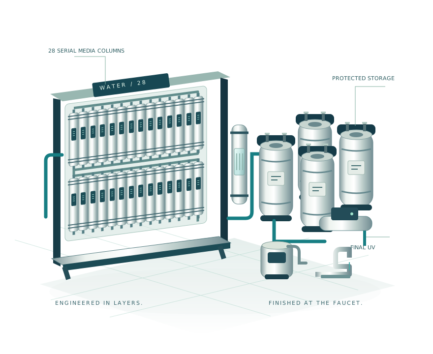
Spatial assembly study: 2 raw kegs, 28 serial media columns, 2 parallel UF elements, 4 treated kegs and a separate drinking branch. Routing, spacing and proportions are illustrative; hardware packaging remains to be finalized.Spatial assembly study: 2 raw kegs, 28 serial media columns, 2 parallel UF elements, 4 treated kegs and a separate drinking branch. Routing, spacing and proportions are illustrative; hardware packaging remains to be finalized.
Spatial assembly study: 2 raw kegs, 28 serial media columns, 2 parallel UF elements, 4 treated kegs and a separate drinking branch. Routing, spacing and proportions are illustrative; hardware packaging remains to be finalized.
28media columns
working in sequence
15 gal/daytotal media throughput
including service & still feed
2purposeful paths
household & drinking

Thoughtfully slow treatment.
Stored water when you need it.Current design targets, not measured ratings.

MORE THOUGHT IN EVERY LAYER

Water is complex.
Your system should
make sense.

One filter cannot do every job. Water brings together distinct treatments, each with a clear purpose—and room to adapt to the source.

Capture grit before it reaches the finer filters. Give targeted media time to work. Protect clean storage. Finish with monitored UV close to the outlet. Then take drinking water through its own distillation and finishing path.

Follow a drop through

FROM SOURCE TO FAUCET

Every stage.
For a reason.

Fast intake. Deliberate treatment.
Two ways to finish.

A BETTER START

Let the right water in.

Screens and a vortex separator intercept coarse debris before two 5-gallon raw-water kegs buffer the fast fill. Fine prefilters protect the stages ahead.

Source → screens & vortex → raw buffer → prefilters

When needed, a separate flow-through ceramic pretreatment module captures fine suspended solids, with optional inline ferric coagulation. Automatic purge removes solids; no batch settling step is selected.

Conditional conditioning and softening are selected for the source. The interactive tour groups stages; the full sequence appears below.

View the complete treatment sequence

Intake: 20-mesh suction screen → intake pump → 40-mesh Y-strainer → vortex separator → 100 µm strainer → 2 × 5 gal raw kegs.

Slow treatment: treatment pump & restrictor → optional sand/garnet → 25 µm cotton → 15 & 5 µm canisters → conditional inline coagulation/contact/additional ceramic MF or UF → optional early UV (no safety credit) → source pH conditioning & conditional Birm → 28-column media cassette → conditional lead/guard softener → 5 µm & 1 µm fines filters → booster → pressure ceramic → two 50 nm UF elements in parallel → 4 × 5 gal treated kegs.

Household: delivery pump/accumulator → monitored UV → short distribution to cold taps/toilet and tankless heater for hot taps/shower. Initial combined peak cap: 3 US GPM.

Drinking: treated storage → distiller → free atmospheric receiver → sanitary transfer pump → coconut GAC/fines retention → optional calcite/fines retention → 2.5 gal drinking keg → chiller → independent monitored UV → short faucet connection. Initial cap: 1 L/min.
THE COMPLETE PICTURE

See the connections.
Understand the barriers.

Continuous pretreatment.
Serial media. Parallel UF.
Two independent delivery finishes.

The complete Water treatment architectureFlow-through pretreatment and 28 serial media columns precede a conditional softener, pressure ceramic and two UF elements in parallel. Four treated kegs feed separate household and distilled drinking branches, each finishing with monitored UV after carbon. Intake / screensvortex · 2 raw kegs Fine prefilters25 → 15 → 5 µm Conditional flow-throughcoagulant / contact / ceramic Source conditioningpH / Birm when suitable 28-column media cassetteall in series · lead / guard samples Hard-source optionlead / guard softener Fines / booster5 µm → 1 µm → pump Pressure ceramicqualified assembly 50 nm UF / 150 nm UF / 2 Protected treated storage4 × 5 gal · isolated banks A / B TWO ELEMENTS IN PARALLEL HOUSEHOLD PATH · INITIAL COMBINED CAP 3 US GPMPump / accumulatorstored water supplies peaksMonitored delivery UVfault → close affected outletShort cold / hot distributionheater on hot branch DISTILLED DRINKING PATH · INITIAL FAUCET CAP 1 L/MINDistillerfree condensate outletatmospheric receiverTransfer / carbonGAC + fines retentionoptional remineralizationDrinking storagesealed 2.5 gal kegprotected gas pathsChiller6–10 °C targetIndependent UVmonitored / fault closureFaucetshort cleanable run FUNCTIONAL DIAGRAM · schematic routing · sample valves, cleaning circuits and optional early UV omitted for clarity

Flow animation explains routing, not measured performance. Carbon remains before final UV. The upstream clarification module is additional to the downstream parallel UF pair. The still discharges freely into an atmospheric receiver before sanitary transfer. Source-dependent modules and detailed sanitation circuits require final hardware selection.

ONE SYSTEM. TWO PRIORITIES.

For daily life.
For your next glass.

The extra work belongs where
it makes the most difference.

THE HOUSEHOLD PATH 01

Make the everyday
feel considered.

Layered filtration, buffered storage and final UV support the water you use throughout the day. Stored water separates quick demand at a tap from the slow contact time the media needs.

20 galnominal treated storage
3 GPMinitial combined peak cap

15 gal/day is the total treatment budget, including service and drinking-branch feed. Storage and peak flow do not increase daily production.

THE DRINKING PATH 02

A little more care.
In every sip.

Distillation adds a separate barrier for many nonvolatile dissolved contaminants. Coconut carbon, optional mineral finishing and chilled storage sit upstream of independent final UV.

~1 gal/dayplanned drinking use
6–10°Cchilled serving target

Distillation requires energy and scale management. Volatile carryover, hygienic transfer and finished-water quality still need verification.

A LOOK INSIDE THE CASSETTE

KDF ×1Catalytic carbon ×3GAC ×4Bone char ×12Zeolite ×3E33 ×2GAC polish ×1Calcite ×2
ALL 28 IN SERIES · LEAD/GUARD SAMPLING BETWEEN KEY GROUPS

PURPOSEFUL MATERIALS

More stainless.
More serviceable.

Metal housings, ceramic elements and replaceable media make the design tangible. Sample points between lead and guard beds help reveal when targeted treatment needs service.

Low plastic is a design priority, with explicit exceptions for seals, pumps, some sensor bodies, gas-filter membranes and source-specific resins. Each exception earns its place.

Service by condition.

Media are replaced on loading, breakthrough or hygiene needs, with 90 days as the maximum cassette age—not a guaranteed capacity.

DESIGNED AROUND YOUR SOURCE

Different water.
A considered response.

Broad-source ambition.
Source-specific treatment.

TARGETED CONDITIONING

Start with the chemistry.

Catalytic carbon and GAC address specified disinfectant, taste and organic targets when the exact media, contact time and capacity are suitable. Source testing determines whether additional treatment is needed.

Know the limits.

The main train retains most dissolved salts. Nitrate, PFAS and other specific contaminants need a qualified configuration and target-specific verification.

Source examples describe design intent. Acceptance depends on chemical and microbial testing, component inlet conditions, capacity and assembled-system qualification.

KNOW WHAT IS HAPPENING

See the process.
Protect the finish.

Arduino-compatible instruments are planned for flow, pressure, pH, conductivity, turbidity, levels and leaks. Hardness needs its own measurement. Factory UV health and independent outlet closure remain essential.

Sensor values help control the process. They cannot prove the absence of microbes, arsenic, PFAS or every chemical contaminant.

WATER / CONTROL CONCEPTPLANNED FUNCTIONS
↝Observe

Flow · pressure · pH
turbidity · conductivity

◎Evaluate

Calibrated limits
valid data · UV health

⊘Protect

Divert · isolate
close affected outlet

Final UV faults must close the affected outlet.

GOOD DESIGN SHOULD BE OPEN

See what
goes into it.

Explore the components.
Understand the tradeoffs.

These are historical USD component allowances from the engineering design, using supplier snippets and estimates recorded in October 2026. Expand any row for the component lead, source and exclusions.

A complete system price depends on the source configuration, final hardware and qualification. Several required items are still unpriced.

COSTS STILL TO COMPLETE

The missing pieces stay visible.

The 28-column cassette and media fill; gas handling, sanitation and sampling; exact controls, analyzers, protection valves and power system; drinking transfer hardware and compact UV; and any source-specific clarification, Birm, nitrate or softening modules still need firm configurations and pricing. Filters below include these unpriced groups individually.

A FEW GOOD QUESTIONS

The details
behind the design.

Is this comparable to reverse osmosis?

The dedicated drinking distiller can reduce many nonvolatile dissolved contaminants to low levels, which overlaps with RO's purpose. The main media/ceramic/UV train does not provide RO's broad dissolved-salt separation. Exact water quality depends on the assembled system and source; neither pathway is a guarantee against every contaminant. A whole-system RO-equivalence claim would be premature.

What are the choices for hard water?

There are several. Sodium- or potassium-cycle ion exchange actually removes calcium and magnesium, and is the present reference for hard sources. NF/RO also reduce hardness, with membrane, pressure and reject-water tradeoffs. Continuous lime/soda or pellet softening can precipitate hardness but adds chemistry and solids management. Distillation separates hardness in the drinking fraction; scaling and energy make whole-demand use a different proposition.

“Salt-free” scale-control devices, TAC and magnets are not credited as hardness removal. The reference softener uses two 1.5 L lead/guard resin beds, but geometry and capacity need qualification. Illustrative lead-bed service is only about 2–3.5 days at 500–300 mg/L hardness and the 15 gal/day basis—not 90 days.

Does inline coagulation need expensive ceramic UF?

No. A suitable ceramic microfilter can capture coagulated solids; UF is not inherently required for that job. Conventional granular filtration is another established route. A published continuous pilot used 0.3–0.5 µm silicon-carbide ceramic with inline coagulation, but that larger pilot used PACl and active cleaning. It does not establish the same chemistry, flow or performance for this small ferric-based design.

A cheap household ceramic candle is not automatically suitable for sustained floc loading or backwash. Select for retention, effective area, seals, ferric residual, sustainable flow and cleaning. This upstream clarification duty is additional to the existing downstream UF pair. Read the ceramic pilot report ↗

What is the coagulant made of?

The proposed options are potable-grade ferric chloride (FeCl₃) or ferric sulfate (Fe₂(SO₄)₃). They form iron-hydroxide flocs that help gather suitable fine particles and organic color for filtration. Dosing consumes alkalinity and can lower pH; chloride or sulfate remain dissolved. Ferric chloride is not chlorine disinfection. No synthetic polymer flocculant is selected.

Coagulant is used only when the source benefits from it. Metered dosing, mixing, contact and ceramic capture operate in a flow-through train, with isolated purge to waste. There is no batch mix/settle/decant step.

Why keep carbon if bacteria can grow on it?

Carbon serves useful taste and targeted chemical functions. It has finite capacity and can support microbial growth, so both the main polish and drinking polish remain upstream of final delivery UV. Protected storage, cleanable short connections and a complete sanitation routine address the other clean-side surfaces. UV does not sanitize tank walls or provide a lasting residual.

Can the drinking water be mildly alkaline?

Yes. Optional calcite remineralization can buffer distilled water and add minerals. The nominal finished-water pH target is 7.2–8.0, within an outer 6.5–8.5 acceptance band and all relevant component limits. Alkalinity, hardness and stagnation need control too. This is a taste and materials choice; a higher pH is not an established general health advantage.

How close is it to something I can buy?

This is an engineering design preview, not an available finished product. The complete assembly has not been built, tested or certified. Exact source conditioning, hydraulics, compact drinking UV, controls, sanitation, power/waste routing and costs remain to be completed. Component-level certifications do not certify this custom system.

The useful next milestone is a fully specified, serviceable assembly followed by source-to-faucet chemical and microbial validation—including storage, stagnation and fault behavior.

THOUGHTFULLY ENGINEERED. OPENLY EXPLAINED.

A clearer path
to your next glass.

Explore the system